Technical diagrams
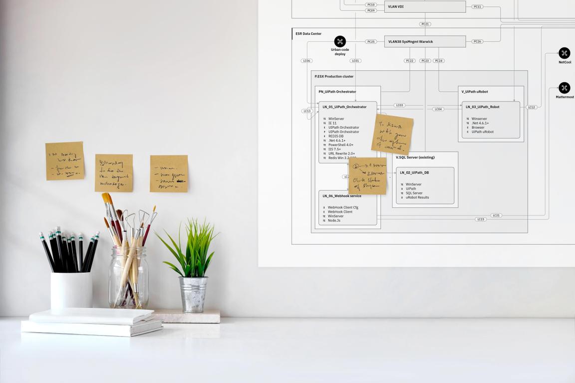
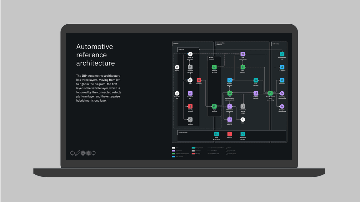
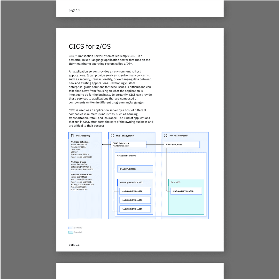
Technical diagrams serve many purposes at IBM. They can be used to describe relationships among the elements of a system, the hierarchy of a certain structure or introduce the idea of an ordering sequence to represent a process flow.
Examples in use
Clarity
When creating a technical diagram, clarity and legibility are paramount. These guidelines were developed to help, as well as ensure brand consistency. Try to follow them as closely as possible. Depending on the tools used to create diagrams, there may be certain limitations, however clarity should never be sacrificed.
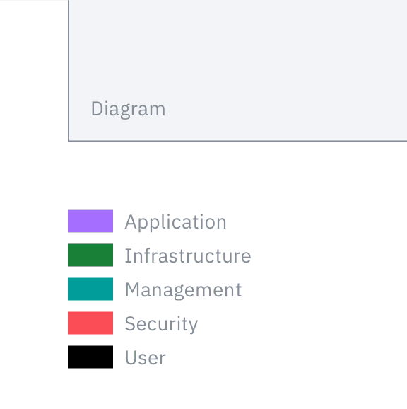
Always add a legend to your diagram, showing the color, line, style and shape conventions used.
Don’t use icons by themselves to represent essential information—always use words, as well.

When a diagram can’t be displayed at 100% scale, offer the user a way to download it or zoom in.
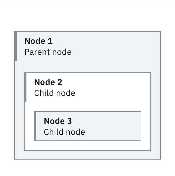
Alternate background fill colors to improve nesting readability.
Avoid redundancy when using shapes, styles, colors or indicator badges.
Don’t mix types of nodes unless they have specific semantic differences that can’t be expressed otherwise.
Carbon
The technical diagrams guidance presented here is meant for diagrams that appear outside of product screens, such as those found in documentation websites, in presentations, on collateral and so on. When creating a technical diagram as part of a product, use the Carbon components and Carbon for IBM Products guidance instead.
Subsystems
Using our technical diagram guidance as a foundation, some teams have expanded on our system. They’ve built a number of discrete extensions, effectively creating subsystems that specifically address their exact use cases. If you work with one of these subsystems, do follow our general guidance, as well as the specific adaptations applicable to your use case. If you believe you have an application that requires new elements, reach out to the IBM brand design team with your proposal for approval. It helps ensure that your technical diagram subsystem adheres to our general guidance, and gives us the opportunity to share it here with all teams.
IT architecture
The IBM Unified Method Framework is the modelling standard used by IBM for IT architecture. When creating an IT architecture diagram, follow the visual guidance developed specifically for this type of diagram. Doing so helps ensure correct interpretation of your architectural model.
The visual vocabulary developed for IT architecture diagrams corresponds to the main elements used in architecture models:
Target IT system
The system being modelled and engineered
Actor
An external IT system or a user interacting with the target system
Node
A collection of deployment units in a location
Component
A modular unit of functionality, which makes this functionality available through an interface
Deployment unit
Nonfunctional aspects of a component
Location
A group representing a geographical area or position
Zone
A group aggregating a number of model elements with a common set of values for a specific nonfunctional requirement
Subsystem
Any subset of the model elements and element relationships of a system
IT architecture diagrams resources
Product documentation
All products created by IBM have some related documentation. Often, this documentation includes various types of technical diagrams, such as flows, process diagrams, network diagrams and so on. Whenever you need to create a diagram representing a system of parts and the relationship between them, start from our general technical diagrams guidance. Various teams have developed subsystems tailored to their specific applications. Check this Box folder for customized kits.

